Vocab
Before we dive into the topic, let me introduce some terms frequently used in this article.
Component
A 2D representation of a mechanical or electric equipment. For example – Transformers, Power generation units, Fuel storage, Water tank, Cooling towers etc.
Map
Google Map or MS Bing Map. Both these maps have equivalent capacities. In my experience Google Map has more recent imagery. For this project we chose to use Bing map because the app needs to work across geographies including China.
Requirement
Following is the overall requirement for this development
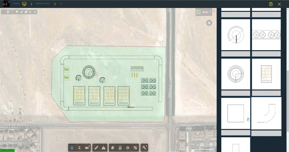
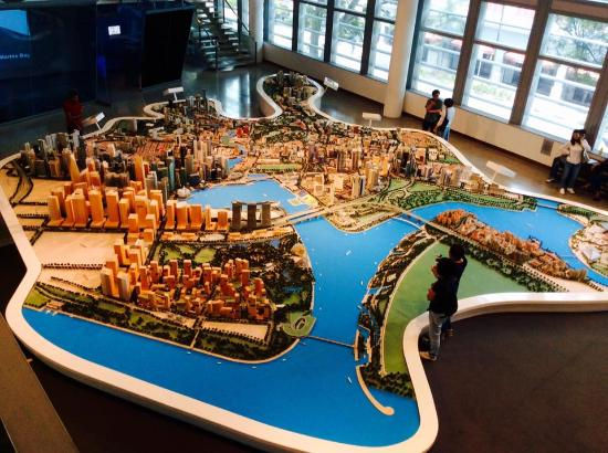
An application where 2D CAD modeler window would have a map in the background. It would be equivalent as if putting things on a physical map. More like a sand model. However, the scale of the components will be such that it would give clear idea of their actual size on the ground.
Implementation
There were following possibilities to achieve this:
- Add the component on map as an overlay NOT SELECTED
It required converting the 2D drawing files to SVG (Scalable Vector Graphics) files using a DWG to SVG converter. SVGs could be inserted on Bing map by resizing them according to the zoom level. Once the component is placed correctly, zoom in zoom out worked well as the SVG would act as a part of map now. The problem with this approach was it needed a third party application to convert DWG to SVG.
2. Add Bing map as an overlay in Autodesk FORGE Viewer NOT SELECTED
The resizing of the map on Forge window did not work well.
3. Bing Map and Autodesk FORGE Viewer in separate canvas which will be placed on top of each other SELECTED
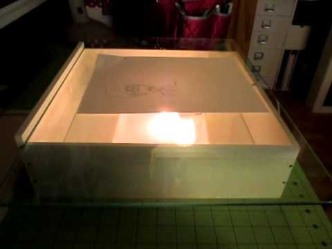
We chose the third option after some trial and error as it seemed the best way to use full capabilities of Autodesk FORGE viewer. Autodesk FORGE canvas was given a transparency value through which underlying map is visible. This required to give transparency only to viewer background and not to the 2D objects. Autodesk support team promptly helped us to find out methods to achieve this.
It’s more like glass tracing
Autodesk FORGE viewer was a good choice as:
- DWG conversion to native Autodesk FORGE viewer format (F2D) could be easily achieved using Autodesk FORGE Model Derivative API on cloud
- Manipulated drawings could be converted back to DWG and published as PDF by Autodesk FORGE Design Automation API
- Autodesk FORGE viewer has great built in features for 2D and 3D model viewing with scope for extension
What is explained here?
The final developed application has many components and functionalities. The interesting problem of syncing the map window with the Autodesk FORGE viewer window was tackled using some tricks. The effect was that these both separate windows started acting as if they are embedded in one another. The next part of the article contains details about the solution we used to achieve this.
Map + Model Synchronization
Zoom Synchronization
This is how the algorithm worked
Step 1 :
Two points in Autodesk FORGE which are 1 meter apart were taken. This can be done in two ways (One-time activity per session)
a) Assuming that the opened drawing is in meters, just take origin and 1,0,0 in model space. Convert these points in page space (referred as world space in code)
_findBoundingBoxAssumingMilimeterUnitsForModelSpace
b) Have a scale in each base template drawing with predefined block name such as “MeterScale”. MeterScale is of 20 meters. Find the bounds of this block and get your 1-meter distance first in Model Space and then in Page Space.
Step 2 :
Map to Autodesk FORGE Scaling Factor (to be calculated on each zoom on Autodesk FORGE)
_getMaptoForgeScalingFactor
Convert the meter distance in Pixels. We now know that X number of pixels are equivalent to 1 meter on Autodesk FORGE canvas. We need to know how much of X pixel mean on the map in meters.
Now, there is catch. This correlation between pixels to distance depends on where on earth the underlying location is. This is vital to calculate resolution at a particular latitude. The maps we see use Mercator projection and the resolution changes with a change in the latitude. So we first need to find the resolution
https://msdn.microsoft.com/en-us/library/aa940990.aspx
let resolution = 156543.04 * Math.cos((referenceLatitude * Math.PI) / 180.0) / Math.pow(2, map.getZoom());
After adjusting the pixel count in maps according to the resolution, we get a scaling factor.
let mapToForgeScalingFactor = twentyMetersInPixelInForge / twentyMetersInPixelInMap;
Step 3 :
If the mapToForgeScalingFactor is less or greater than 1, that means either Autodesk FORGE or Map needs to adjust its zoom level. adjustMapToSyncWithForge() does exactly that. It checks the current Autodesk FORGE scaling factor by and uses it to set new zoom level for map.
There are around 22 to 24 discrete zoom levels on map. As per the scale factor, the map zoom is set to the nearest matching zoom level. Still, it’s not a perfect scale match. So, we need to fill the difference by adjusting the FORGE viewer zoom setting.
We need to fine tune the Autodesk FORGE zoom level to match it perfectly with Map. This is achieved by listening to the view change events of the map and adjusting Autodesk FORGE Zoom accordingly.
this.viewChangedHandlerId = Microsoft.Maps.Events.addHandler(map, 'viewchangeend', this.mapViewChanged.bind(this));
mapViewChanged and adjustForgeCameraToSyncWithMap() takes care of the zoom fine tuning.
Pan Synchronization
- To be able to move map and Autodesk FORGE in unison, we need to decide a point on map and a point on Autodesk FORGE which will be our anchor points.
mappingInformation.forgeLocationInWorldCoords and mappingInformation.geoLocationOnMap
- Once we get this information, get the pixel coords of the Autodesk FORGE anchor point
- Get pixel coords of Map anchor point
- Get the difference in pixel coords
- Get the current center of map in pixel coords
- Subtract this difference from current Center pixel coords. We get a new center of map in pixel coords
- Convert this new center in pixel coords back into Geo coords
- Set this new point as a center of map and it will follow Autodesk FORGE pans just like charm.
We can choose when to relay the events and when to stop. Thus, Lock and Unlock can be easily done. By this, Map and Viewer becomes detached and it makes it possible to shift anchor points in case user wants to move the drawing to a new location on map.
This is how it looks
This is a demonstration of final application. Apart from map and Autodesk FORGE viewer syncing, this also showcase other features of the application, such as drag-drop, model editing, rules verifications, measurements, publishing and sharing of the drawing etc.
Conclusion
Using Autodesk FORGE Viewer capacities mixed with our creativity provided seamless ways to interact with maps. I believe that with little efforts this trick can be used to synchronize any CAD viewer with Google or Bing Map. We found that Autodesk’s Forge Platform is not only a great tool for development of 2D and 3D apps, it also is highly customizable to suit the user’s needs.